
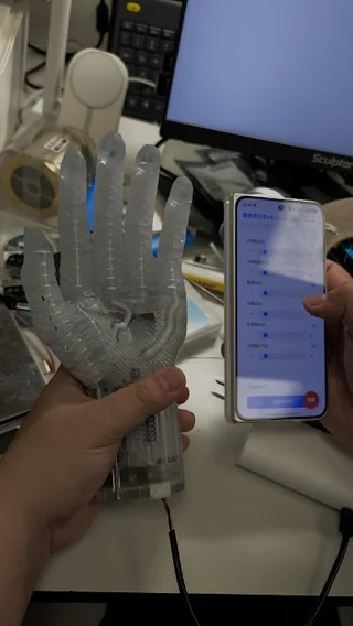
We've been iterating on SoftSync FlexHand V1 over the last few weeks. This update focuses on two mechanical improvements: Switched to a new soft material for better compliance. Combined braided reinforcement with additive manufacturing to improve durability. The demo shows thumb-to-index, thumb-to-middle, and thumb-to-ring pinch generated with a simple drag-and-drop programming workflow. No pre-training was used. I'd love to hear any feedback, especially on the mechanical design or the control workflow. submitted by /u/LSunround [link] [Kommentare]
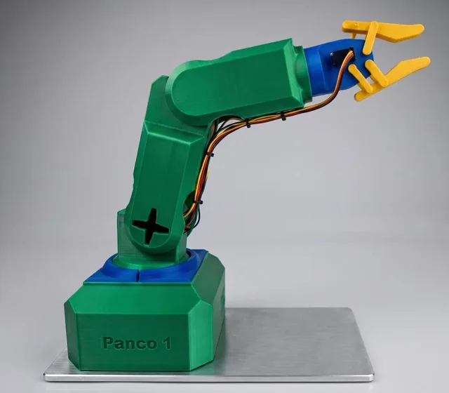
Hey r/robotics ! After months of design and testing, I finally have a working 5-axis robot arm fully printable in PLA or PETG — no CNC, no laser cutter, just your printer. Here's what makes it different: - 5 axes (shoulder, elbow, wrist, gripper + base stepper motor) - ESP32 brain — totally open-source firmware - Electronics BOM under $100 sourcing parts yourself - Full wiring diagrams, assembly guide, and source code included The V1 is already fully operational and tested. I just launched a Kickstarter pre-launch page to fund the V2 (better rigidity, internal cable routing, improved gripper). Happy to answer any questions about the design choices, print settings, or the electronics. AMA! https://www.kickstarter.com/projects/pancoarmmk01/panco-arm-mk-01 submitted by /u/ConferenceFew7697 [link] [Kommentare]

It's underappreciated how close to perfect the performance of a robot needs to be to be profitable, and getting there takes an enormous amount of experimentation across data, hardware, and machine learning. In CV or LLMs, the same test set can be used forever. However in robotics, each test needs to be manually reset and evaluated for success. This does not scale, especially when success is measured as the difference between 98% and 99% success. Here's what that scaling problem costs in practice. Measuring a policy at 90%+ level with any confidence takes 40-50 rollouts per checkpoint (
Hi everyone, I'm currently working on my bachelor's thesis, where I'm designing a modular hybrid robotic gripper. The idea is to combine: A rigid PLA backbone that transmits gripping force. A replaceable TPU insert attached using a dovetail. A compliant contact pad that deforms locally to conform to different object shapes. Unlike a Fin Ray finger, I don't want the whole finger to bend. I only want the contact pad itself to compress , almost like a soft mattress, while the rigid backbone continues transmitting the gripping force. My challenge is choosing the internal structure of the TPU pad. I've already tried: Vertical pillars (1 mm thick, initially 9, then reduced to 5). These turned out much stiffer than expected. In FEA, almost all the stress concentrated at the pillar joints and the contact surface barely moved. A completely hollow pad, which deformed very easily, but I'm concerned it may become too compliant and reduce force transmission. So I'm looking for an internal structure that provides controlled local compliance: The contact surface should deform under load Deformation should be distributed rather than localized. The rigid backbone should still transmit most of the gripping force. It should be printable with FDM using TPU. It should also be practical to model in FEA. My questions are: Is there a known lattice or compliant structure commonly used for this type of application? Should I be thinking in terms of lattice geometry, thickness, relative density, or something else entirely? Are there any compliant mechanism patterns (diamond, X-lattice, zig-zag, auxetic, etc.) that are known to behave like a compressible contact pad? If you've designed soft robotic fingers or compliant structures before, what worked well and what should I avoid? I'd really appreciate any advice, papers, or examples. I'm trying to make design decisions that I can justify academically rather than simply saying "this one seemed to work." submitted by /u/ghanoushi [link] [Kommentare]
Hello, I completed the Odin Project about a year ago, and now I'm looking to get into lower level programming for robotics and mechanical control systems. I'm a college student starting into a mechatronics degree, but after looking over the curriculum, I'm not sure how in-depth my uni goes into the programming side of things. They only have one coding course and 2 PLC courses. I've been watching the PBS Crash Course computer science series for a basic understanding of how computers work at the hardware level, and I'm also reading a couple of electronics books, but I'm having a hard time finding any good resources for learning C++. Does anyone know of any good resources? Is it too ambitious of an undertaking to learn this on my own? Thank you for your responses and insight. submitted by /u/Strange_Bonus9044 [link] [Kommentare]
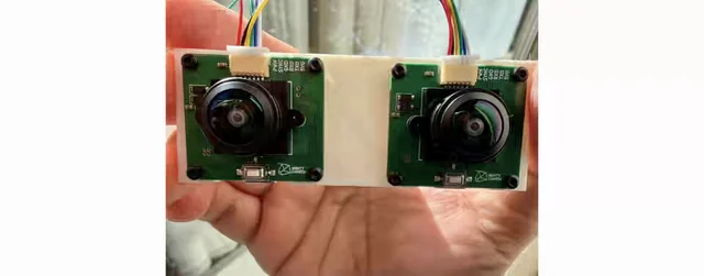
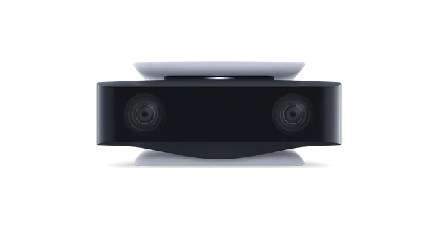
This is my project, Mighty Camera. It is essentially a monocular SLAM camera running entirely on tiny onboard compute. See my past posts for details. Mighty also supports combining multiple cameras and synchronizing them to produce frame-level synced streams. In this setup, I’m using that hardware synchronization to generate depth with SGBM, while it also produces VIO pose. submitted by /u/twokiloballs [link] [Kommentare]
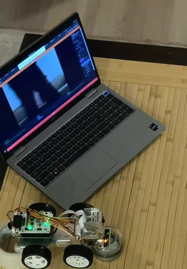
Follow-up to the v2 trajectory post and the noise characterization experiment. v3 adds image-based visual servoing. The problem with v1 v1 tracked horizontally by steering the car body. Ackermann steering has a minimum turning radius — if the tag moves outside a cone in front of the car, the only recovery is a multi-point turn. The camera was locked forward and the car had to point at what it wanted to see. IBVS decouples the camera from the chassis. The pan/tilt gimbal tracks the tag in pixel space regardless of where the car is pointing, and the car centering logic works from the gimbal's pan angle rather than raw image error. The camera can follow a target that the car physically can't yet reach. What v3 adds IBVS core — pan and tilt are driven by pixel error feedback: eu = tag_x − cx, ev = tag_y − cy. Error is smoothed with an EWMA (alpha=0.8), a 10px deadband prevents hunting at center, and corrections are capped at 2° per frame. The result is a gimbal that follows the tag continuously rather than only when the car is pointed at it. Four operational modes — ibvs_test (gimbal only, no drive), manual_ibvs (gimbal + WASD), rat_chase (gimbal + autonomous centering + forward drive), and world_ibvs (full v2 dual-tag world frame behavior). The modes let each layer be validated in isolation before combining them. rat_chase — the autonomous mode shown in the video. Car centering derives a steering angle from the gimbal's current pan angle via a feed-forward gain, then drives forward at a configurable speed and stops at a distance threshold. The car is on a test rig in this clip so the wheels are suspended — this is a hardware-in-the-loop simulation of the drive logic before putting it on the floor. ibvs_anchor_mode world frame — tag0 alone is now enough to anchor the world frame. First detection seeds T_world_anchor; every subsequent frame derives world → car_base from that anchor and the current tag0 pose. No second tag required. The full URDF renders in RViz2 and the car trajectory publishes live. Trajectory visualizer — trajviz.py reads the PLY files output by tf_bridge and produces an interactive Plotly HTML with a color gradient over time, cubic spline overlay, and sliders for spline order and smoothing weight. What the video shows The car is suspended on a test rig — wheels off the floor — running in rat_chase mode. Pan/tilt hunts briefly at the start while the EWMA settles, then locks onto the tag and tracks it. The gimbal motion looks smooth on the car itself; some snappiness is visible in the camera output feed, which is the per-frame correction still present at the edges of the lazy band. Drive and steering commands are being issued but the wheels aren't in contact with anything. Next step is putting it on the floor and running it for real. Bugs worth mentioning TF never broadcast in ibvs_test/manual_ibvs. tf_pub.on_frame() was only called inside _do_chasing(), which the ibvs_test and manual_ibvs branches never reach — they return early. Pi was detecting the tag correctly but zero messages reached tf_bridge. Fix: added the on_frame() call directly in the early-return branch. Z filter rejecting all valid frames — twice. The first version checked car_base_pos[2] against a floor threshold; car base is at Z≈0 so every frame failed. Fixed to check camera height instead. Second version: valid camera height readings clustered just below the threshold (0.000–0.054m vs 0.055m cutoff) and still got rejected universally. Root cause was that I was physically lifting the car during testing so Z filtering is inappropriate in that context. Made the filter an opt-in ROS2 param, defaulted off. Velocity gate blocking hand-carried movement. The jump gate inherited from v2 was set at 10cm — fine for autonomous driving, but every footstep when carrying the car exceeds that. Result: 62 skipped frames in 11 seconds, 2 trajectory points recorded. Added a separate ibvs_max_jump_m param (default 1.0m) for the ibvs_anchor path. What's next Put rat_chase on the floor with the wheels down. The steering and drive logic is implemented and confirmed sending commands — it just hasn't chased anything yet under its own power in v3. That's the next session. References Post history v2 noise characterization experiment v2 trajectory post v1 tag chaser PiCar-X introduction Hardware / code PiCar-X on Amazon Git repo submitted by /u/okineedaplan [link] [Kommentare]
Following up on my last post about this robot project (which I'm currently working on with a Raspberry Pi)—I thought I'd share an update on the project's progress, since I ran into a problem that took me a bit of research to figure out, and I was also able to reflect on it thanks to the very valuable feedback I received. (https://www.reddit.com/r/raspberry_pi/s/eCKPFWwPhk) The issue While testing the 4 DC motors from the web interface, I noticed something off: sometimes the robot would suddenly lurch forward at full speed when I'd only tapped a key once, and other times there'd be a noticeable delay between pressing a key and the motor actually responding. Not a one-off glitch — happening often enough that I couldn't trust the controls. What was actually going on After digging into it, the culprit was the PWM signal I was using to control motor speed. I was using RPi.GPIO's software PWM, which relies on a Python thread toggling the pin at precise intervals to simulate the signal. The problem is that thread has to compete for CPU time with everything else my server is doing — streaming gyroscope data 20 times a second, running the radar scan, handling Flask/SocketIO requests. When the Pi got momentarily busy, the PWM timing would drift, which explains both symptoms: a duty cycle spike (sudden full-speed lurch) or a delayed update (the motor not getting the new speed in time). The fix Switched to pigpio, which runs as a separate daemon (pigpiod) in the background. Instead of my Python code generating the PWM signal itself, it just sends simple commands to this daemon, which handles the actual signal generation independently of whatever else the Pi is doing. So far the difference is noticeable — no more random speed spikes during testing. The other thing I added: a watchdog Separately, I realized there was a bigger risk I hadn't addressed: the robot is controlled entirely over WiFi through a browser. If the connection drops for any reason while it's moving forward, there was nothing stopping it from just... continuing toward whatever's in front of it. So I added a watchdog thread on the server side — it tracks the timestamp of the last command received, and if more than 500ms pass without a new one, it force-stops the motors automatically. Independent safety net, regardless of what causes the disconnect (WiFi hiccup, browser crash, whatever). what I plan to do next Mechanical redesign: dropping from 4 driven wheels to 2 front-driven wheels + a rear caster wheel, mainly to simplify trajectory control (the 4-wheel setup made it hard to drive perfectly straight) Mounting HC-020K encoders on the front wheels for actual odometry instead of relying purely on the gyroscope (which drifts over time) Eventually fusing gyro + encoder data to get a stable heading estimate Repo's here if you want to poke around: https://github.com/enzocolombat/EC-Hub Genuinely curious what people think of the pigpio + watchdog approach — is there a cleaner way to handle the real-time PWM issue I'm missing? And for anyone who's done the encoder + gyro fusion thing on a budget robot, would love to hear how you approached it before I dive in. submitted by /u/Pasteque9000 [link] [Kommentare]
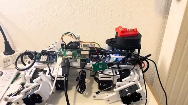
Ever since the post from last time: https://www.reddit.com/r/robotics/comments/1u1iql9/cubic_doggo_update_wobbly_imu/ I have tried to implement all the suggestions from the previous posts (thank you guys :)), and then spent way too much time tuning the PID, hoping it could perfectly balance the robot without wobbling. And the first video is showing my best full PID result so far: it can achieve perfect balance, BUT with randomly occurring spasms. A bubble level is added on its head. After standing+leveling, the platform is put on a slope. The bubble shifts, and the robot is trying to adjust it back Still cannot figure out the reason after quite some updates, though, but 50Hz reading rate with ~10ms lag, and legs lifting the whole body weight while changing tiny position probably are the culprit. So maybe it really doesn't need perfect leveling; it just needs some corrections on a slope. The second video is with P-only, fast reacting and no oscillation. Maybe this is showing the limitation of PID as compared to reinforcement learning? I am not at all sure. For now, though, I still want to see how P-only leveling performs during a walk gait. Link to the previous walking post without IMU: https://www.reddit.com/r/robotics/comments/1tghftd/cubic_doggo_full_github_record_it_can_now_walk/ submitted by /u/SphericalCowww [link] [Kommentare]