

Why we replaced RocksDB with Fractal ART, an on-disk adaptive radix tree for object storage metadata.

Game industry legend Wouter van Oortmerssen on surviving in Early Access and the difficult task of standing apart from Minecraft.

The market for computers' silicon brains has quietly grown from the size of Major League Baseball to the size of the global cement industry, and it is doubling. Computing is bigger than you think, and getting bigger faster than you can update your intuitions about how big it is.
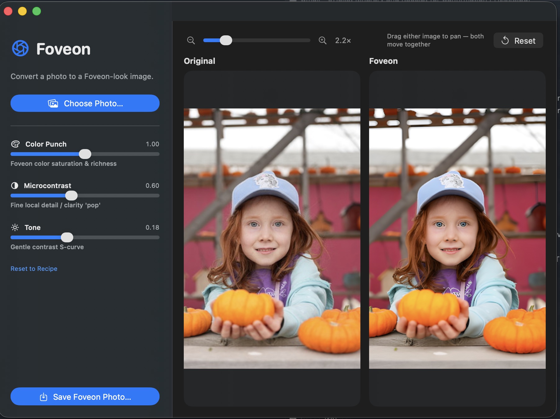
Foveon A neural sensor translator. Takes a photo from any Bayer-array camera and renders it as if it were shot on a Sigma DP2 Merrill — the Foveon X3 stacked-sensor look, with the colour and microdetail Foveon is famous for, on hardware you already own. Under the hood: a modified U-Net with an extra layer injected between the encoder bottleneck and the upsampling decoder. The injected channel carries a one-dimensional encoding of three-layer pixel-stack structure — the B·G·R photodiode column that a Foveon sensor captures and a Bayer sensor can’t. Trained end-to-end against matched Bayer → Merrill scene pairs. U-Net+1D Modified U-Netwith 3-layer pixelinjection at bottleneck Bayer → X3 Bayer CFA in,Foveon X3 stacked-sensor look out DP2 Merrill Trained on matchedscene pairs againstSigma DP2 Merrill ⤓ Download Foveon.dmg macOS 13+ · Apple Silicon 33 MB · signed DMG installer · unverified-developer gatekeeper: right-click Open the first time Foveon — macOS app. Choose a photo, drag the sliders, save the result. What it is Most digital cameras capture colour through a Bayer colour filter array: each photosite sees only one of R, G, or B, and the other two channels are interpolated from the neighbours (demosaiced). It’s efficient, but it costs you. The interpolation introduces colour fringing on sharp edges, smears fine detail, and produces the “digital” micro-contrast that even high-end Bayer cameras can’t fully shake. The Foveon X3 sensor — Sigma’s now-rare design used in the DP1, DP2, and DP3 Merrill cameras — works the way colour film does. Three photodiode layers are stacked vertically at every single pixel position. The top layer absorbs blue, the middle layer green, the bottom layer red. Every pixel captures the full colour. No interpolation, no demosaicing artefacts, no false detail. The result is the “Foveon look”: extraordinary microdetail and a particular colour rendition — warm, dimensional, almost slide-film — that people build entire camera systems around. Foveon (the app) is a neural network that learns the mapping between the two. Feed it a JPEG or RAW from a normal Bayer camera (phone, mirrorless, DSLR) and it predicts what the same scene would look like shot on a Foveon X3 sensor. Geometry stays the same; colour, tonality, and micro-detail rendering shift toward the Merrill side of the training distribution. Bayer vs Foveon — the structural problem Bayer CFA One colour per pixel R G ×2 B Each photosite captures exactly one colour. The other two channels are guessed from the neighbours. The guess is what creates the “digital” signature. Foveon X3 Three layers per pixel red (bottom) green (middle) blue (top) stacked photodiodes, one per pixel Every pixel records R, G, and B separately at the same location. No interpolation. No false colour. The dimensional quality Merrill shooters chase. The architecture The core is a standard convolutional U-Net: an encoder that downsamples the input image into a compact feature bottleneck, paired with a decoder that upsamples back to full resolution, with skip connections at every level so fine spatial detail survives the trip through the bottleneck. The modification is a single new layer dropped in between the encoder’s final downsampling block and the decoder’s first upsampling block: a 1D pixel-stack injection layer that concatenates a one-dimensional encoding of how colour absorbs through silicon depth on a real Foveon sensor — blue first, then green, then red. The decoder learns to use this prior to reconstruct the kind of inter-channel coupling that real X3 captures exhibit — chroma that’s registered with luminance instead of interpolated against it. U-Net architecture diagram. Encoder ENC1 (C=64) → ENC2 (C=128) → ENC3 (C=256) → ENC4 (C=512) → Bottleneck (C=1024) → 1D Pixel-Stack Injection (B·G·R depth prior) → DEC4 (C=512) → DEC3 (C=256) → DEC2 (C=128) → DEC1 (C=64) → output, with skip connections from each encoder level to the matching decoder level. Encoder (blue) downsamples the Bayer input. The 1D injection layer (orange) concatenates the Foveon B·G·R depth prior at the bottleneck. Decoder (purple) upsamples back to full resolution. Skip connections (dashed) carry pre-bottleneck spatial detail across to the matching decoder level — standard U-Net, drawn here for completeness. The novel piece is the orange block. Why inject at the bottleneck The encoder has just stripped spatial resolution to focus on semantic content; the decoder is about to reconstruct it back. That’s exactly the moment to inject the prior that says “reconstruct as if the sensor were stacked, not mosaiced.” Inject earlier and the encoder learns to ignore it; inject later and the decoder has already committed to a demosaic-style chroma reconstruction. Why one-dimensional The injection encodes the order in which colour absorbs through silicon depth on a real Foveon sensor — blue at the top, green in the middle, red at the bottom. That ordering is a 1D signal per pixel column, not a 2D spatial structure. Keeping it 1D keeps the parameter count low and forces the network to learn the inter-channel coupling rather than memorise a per-region lookup. Training The model is trained end-to-end against matched scene pairs: the same subject captured simultaneously by a Bayer-sensor camera and a Sigma DP2 Merrill, the two images aligned and cropped to identical framing. The Bayer image is the network input; the Merrill image is the reconstruction target. STEP 1 Capture matched pairs A Bayer-sensor camera and a Sigma DP2 Merrill are tripod-mounted side-by-side. Each scene is photographed simultaneously by both. We bias capture toward the categories where Foveon rendering differs most visibly from Bayer: outdoor light, foliage, skin tones, fabric, water, metallic surfaces. STEP 2 Align & crop For each pair we run a homography-based alignment (feature-matched on luminance) so the two images share an identical pixel grid despite the different sensor sizes, focal lengths, and viewpoints. The aligned tiles are cropped to common framing and resampled to a shared resolution. Misaligned pairs are filtered out. STEP 3 Develop the Merrill target DP2 Merrill RAW (.X3F) files are developed in Sigma Photo Pro with neutral parameters — zero added sharpening, native colour profile, no creative tone curve. This is the “ground truth” the network is asked to predict: what the X3 sensor saw, minimally interpreted. STEP 4 Tile & augment Each aligned pair is sliced into overlapping 256×256 tiles for training (the U-Net handles arbitrary input sizes at inference, but training on fixed tiles keeps batches efficient). Augmentations: random crop, horizontal flip, small rotation, exposure jitter on both halves of the pair in lock-step. STEP 5 Loss composition Three components, summed with weights tuned to keep colour and detail in balance: L1 pixel loss anchors absolute colour fidelity; VGG perceptual loss carries microdetail and texture (the network learns the Merrill look, not just the average pixel value); a small TV smoothness penalty keeps the output from inventing sharpening artefacts in flat regions. STEP 6 Train & validate AdamW optimiser at lr = 2e-4, cosine schedule, mixed-precision on a single 24 GB GPU. Batch size 16 tiles. We hold out roughly 5% of pairs as a validation set stratified by category (skin, foliage, fabric, etc.) so the model isn’t accidentally memorising a few scenes. Best checkpoint is the one that minimises validation perceptual loss, not L1 — perceptual loss tracks the X3 look more reliably than pixel error. What it produces A schematic comparison: what the same uniform skin patch looks like coming out of a Bayer demosaic pipeline (left) versus what the network predicts the Merrill would have rendered (right). The Bayer side has slight chroma drift between cells; the Merrill side is uniform. INPUT Bayer demosaic visible chroma noisebetween adjacent pixels —the demosaic signature OUTPUT Foveon → X3 look uniform chroma per region,microdetail preserved —the Foveon X3 signature The app Foveon ships as a native macOS app with a clean three-pane workflow: pick a photo on the left, watch the preview update on the right. Three sliders shape the conversion: Color Punch Controls how strongly the Foveon colour rendition is applied. At 0 the output sits closer to the original Bayer colours; at 1.0 (default) the full Merrill warmth and saturation come through. Microcontrast The Foveon look isn’t about sharpening — it’s about fine local detail clarity. This slider lifts that quality on top of the network output without introducing the halo artefacts that conventional unsharp masking would. Tone A gentle contrast S-curve in the output highlights and shadows. Default 0.18 matches Sigma Photo Pro’s neutral tone; push it for a more cinematic look, drop it for a flatter starting point you can grade externally. Drag either preview panel to pan; both panels move together so the same crop is always in view on both sides. Reset snaps the view back to fit, Save Foveon Photo… writes the result. Install & use Foveon runs natively on Apple Silicon. A 24-megapixel input converts in well under a second on an M2; the model uses MPS for inference and stays within ~3 GB of unified memory. ⤓ Download Foveon.dmg macOS 13+ · Apple Silicon · 33 MB Open the DMG and drag Foveon.app into Applications. First launch: right-click the app and choose Open (the DMG is signed but not notarised by Apple yet, so Gatekeeper asks once).

Hello all, I am trying to recreate this mechanism as a personal project - and I am really having trouble wrapping my head around how it works. The knees and below make perfect sense, but the hips are throwing me off. What is the purpose of the 2 perpendicular motors at the top? The ones facing horizontally? And how does the rest of the hip fit in with that purpose? I hope this question makes sense. Here is a research paper showing another angle and a more mechanical breakdown. https://arxiv.org/html/2512.16705v1#S4.F3 Also Nvidia GTC 2026 is where the original clip is from (2:11:36) further in the video it shows a side view: https://www.nvidia.com/gtc/keynote/ submitted by /u/halxcyion [link] [Kommentare]
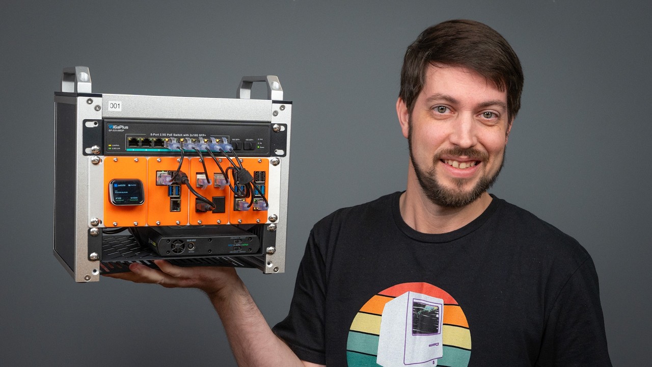
I built a 10-inch mini rack from aluminium extrusions and I had a lot of fun doing it. I want to share my build in this post. In January of 2025, Jeff Geerling released a video about 10-inch mini racks. I was absolutely oblivious to this new trend, and I instantly knew that I wanted to build one for myself some day, although I didn't have a real use for one. That said, I've been working on a virtualization project recently and I've bought six 1L PC's (three for each simulated datacenter). Because these 1L PCs are small, they have huge external power bricks. As these mini PCs are also connected to two networks, they create a huge mess on my desk. Finally a reason to build a mini rack, to tidy things up! There are a few different brands of mini rack for sale, but I wanted to make one for myself. Prebuilt racks (kits) are not cheap for what they are so I wanted to try and see if I could build one myself for less money. Turns out you can buy 20mm aluminium extrusions and accompanying components to build your own rack. (Aluminium extrusions have a standardized 'groove') Aluminium extrusions are bars with a groove on all four sides. These bars have a standard format and you can slide all kinds of equipment in there and lock it in place with set screws. It seems to be used a lot for home made 3D printers, CNC machines and whatnot. In the picture above a special corner piece is used to connect three bars together, fixed in place with set screws. The L-brackets can be used to create T-sections within a frame to sturdy the structure and provide additional mounting points. In my rack, the middle post carries the back of the shelves holding the mini PCs. These sliding cage nuts (M5) can be used to attach anything anywhere. In this example we used four of them to hold the side panels in place. These cage nuts can also be used for their intended purpose: mount 10 inch rack-mount equipment. In this picture below, some cage nuts are left that hold the side panel in place. Also notice in the upper left that I've used cage nuts to attach some black cable tie holders that in turn keep cables in place. The computer trays I planned on ordering 10 inch 1U shelves and be done with it. Unfortunately these metal shelves are too expensive for my taste and would have cost more than the aluminium frame including components (I need 8 shelves). Many 10-inch rack builds - such as the ones featured by Jeff Geerling - use 3D-printed face plates to mount various kinds of equipment. Jeff showcased some of these models in separate videos. That said, I decided against using 3D printed shelves. First of all, I don't have a 3D printer and as useful as 3D printing can be, I feel that 3D printers often turn plastic into landfill. I'd probably feel differently if (more) sustainable materials would have been used1. So instead, I chose to order cut-to-size aluminium sheets and I used the L-brackets to hold them in place. The aluminium shelves turned out OK, but they are not ideal. The 1mm thick plates do bend slightly under the weight of the computers, although it's still fine. Aligning the four L-brackets on the same horizontal plane was a pain. Filing off the sharp corners of each plate was no fun, I should have ordered them with rounded corners. I think these aluminium plates create an open design that is better for keeping the machines cool. There are many 10-inch self 3D models available for these 1L PCs but they all create a tight collar around the front bezel of the computer, which looks amazing, but I don't think it's great for airflow. Regular metal shelves would also have been fine. 10 inch power distribution As you can see below, the backside shows the internals of the case are a bit of a mess2. The truth is that I've should made the rack at least 1U higher to accommodate the very lengthy cabling of the power bricks. All the cabling does fit, but it's not easy to make it clean looking and also give the power bricks - which lie at the bottom - some airflow. No price for cabling management and neatness, that's for sure I've used two 10-inch rack mount power distribution units from Brenenstuhl. They were cheap but they unfortunately didn't fit in a horizontal position. The PDUs are the only actual 10-inch rack-mount component in the entire build and the fact that they didn't fit felt ironic. The cause is simple: in a 19-inch or 10-inch rack, the square holes holding the cage nuts are 'flat sheets', so the power cable sticking out of the side of the PDU can flow behind those square holes. If you use the 20mm aluminum extrusions, there is a 20mm bar in the way. This is why I had to mount the PDUs vertically, which did work fine. At the top, the PDUs are kept in place with another L-bracket clamping the PDUs firm against the rail. The external power bricks of the 1L PCs' are a huge pain. Having six cords and external adapters was absolutely no option for me, I wanted a fully self-contained rack. If you ever build your own rack, try to use computers that have a power supply build-in. I wish I could power these 1L PCs with a 'power shelf'. In this case, a power supply with enough capacity to sustain these PCs at the required voltage and with the proper brand-correct power jack, maybe like this. Cooling All power sockets are in use by the six 1L PCs and the two network switches, so how are we going to power the two cooling fans3? Fortunately there exist USB-to-fan-header cables. It feels dirty but it isn't. USB is only 5 volt but these adapters contain a boost converter that outputs 12 volt for the fans. The power draw of these fans (around 1W) is well below the threshold of 4.5W for a USB3 port. The open backside probably doesn't help with cooling and Ideally I'd fill in the gaps. Due the the irregular shapes, I feel it's too much effort. I do feel a proper airflow at the front of the 1L PCs, so I think it's 'certified good enough4'. Networking The 1L PCs have two network connections, one to each switch. The 3Com switch at the top is 1 Gbit, the TRENDnet switch is 2.5 Gbit. I used the Conceptroning ABBY12G USB3-to-2.5Gbe adapter to connect the 1L PCs to the switch. The 2.5 Gigabit network is a backend network for live migration of virtual machines amongst other traffic. I'm able to achieve line-speed with both iperf3 and virtual machine migrations. The gigabit 3com switch is at least 26, maybe 27 years old! The rack has become a bit crowded due to all this network connectivity, as seen on earlier pictures. It didn't help that I ordered short UTP cables that are quite stiff. Panels The side panels are sheets of anodized aluminium which look good, in my opinion. I forgot to order panels for the top and bottom. Therefore, I decided to go with some wood panels instead of aluminium sheet metal. A local shop offers scrap wood for peanuts and also cuts it to size for a 'few peanuts more'. Very handy if you don't have the right equipment to make straight, clean cuts of wood. Although not pictured, the bottom panel is kept in place with screws locking into cage nuts. These screws also hold the rubber feet in place. Problems A lack of access to the VGA/DP ports: If I lock myself out of a machine, I need to remove one or more fans and connect a VGA/DP cable to the back of the affected machine. This also means moving a lot of UTP cables to the side. I can attach a keyboard to the front but attaching a monitor is thus a real pain. In more regular rack builds, you can add 'keystones' that extend ports to a panel on the outside of the case, where you can connect to an interface without any issue. Cost Item Total Aluminium sheets 82.95 € Aluminium extrusions 26.22 € Rack mount small items 79.96 € wood 7 € shipping costs (over all orders) 20 € USB to 2x 4-pin fan header 12 € 10 Inch PDU 2x 43 € Network cables 42.15 € Total Price 313.28 € All prices include 21% Dutch sales tax. The total price excludes the two Noctua fans, which would probably add another 40 euros. The price is a bit inflated because I overbought small items for rack building. If I opted for wood paneling instead of aluminum panels, that would probably also cut the paneling cost in half. How I use this mini rack The mini PCs are running Debian and they all act as virtualization hosts, using KVM. The gigabit ports are used for the management and provisioning network (PXE+TFTP+iPXE+HTTP). The 2.5Gbit network is used for virtual machine migration and a VXLAN network that encapsulates all the different virtual machine networks. By default, this rack is off. When I want to use it, I turn on a Zigbee power adapter and after a delay, wake-on-lan packets are sent to all six machines to power them on. Power consumption The two switches, two fans and six 1L PCs together use around ~90W idle. Evaluation I'm quite happy with this build. Cost was acceptable, I think it looks decent enough and it really cleans up my desk. Although cable management is clearly not my strong suit, I feel it's an overall improvement. Maybe a few handles for carrying would be a nice future addition, but for now this rack is finished. Did I save any money? I'm not so sure. Acknowledgements Jeff Geerling for introducing me to 10 inch racks This build by Logan Marchione inspired me to further look into aluminium extrusions If you feel differently about 3D printing that's OK. I'm not looking for a discussion or argument about the topic, I'm only stating my motivations. ↩ it's so, so much cleaner than the mess of wires on my desk. I'm already happy with this improvement. ↩ The fans I used are of different size and type, in part because it's what I had lying around. ↩ https://www.youtube.com/SuperfastMatt ↩ Solar Status 71 TiB NAS Projects fio-plot Showtools Storage Fan Control Grafana Dasboard for storage metrics Categories Apple Development Hardware Infrastructure IT Linux Networking Projects Security Solar Storage Uncategorized ZFS Archive 2026 2025 2024 2023 2022 2021 2020 2019 2018 2017 2016 2015 2014 2013 2012 2011 2010 2009 2008
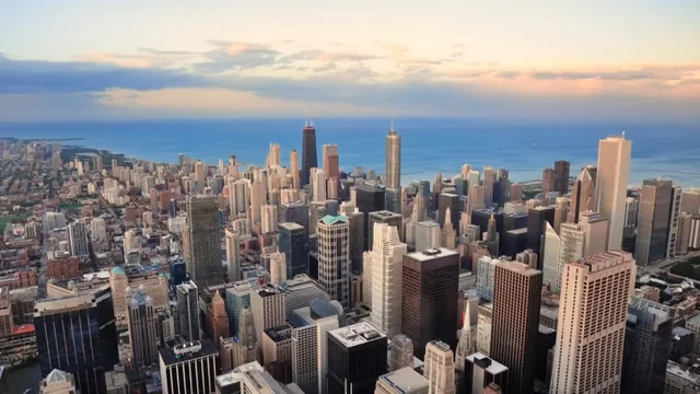
We brought the robot world to Chicago. At Automate 2026, Faraday Future showcased our full EAI robot lineup on the show floor — humanoid, bionic, and mobile manipulator robots, powered by one brain across multiple forms. From the All-New Futurist to our new Faber mobile manipulator series, the FF EAI Robot World drew strong attendee traffic and major media coverage throughout the show. This is only the beginning of robots stepping into real-world life. Learn more: https://robotics.ff.com/us/ submitted by /u/FaradayFuture_FFAI [link] [Kommentare]

Drop in the zip Claude gives you. hatchr renders every screen and hands you a private link to share.
A deep dive into how Ordinary manages structured events in a multi-tenant hosting environment.
The new strikes come in response to an Iranian drone attack on the Ever Lovely in the Strait of Hormuz.