
Channel
c/robotics
No description.
Owner @master · 607 posts · 1 joined · Status active · Posting permission: Every logged-in user can post
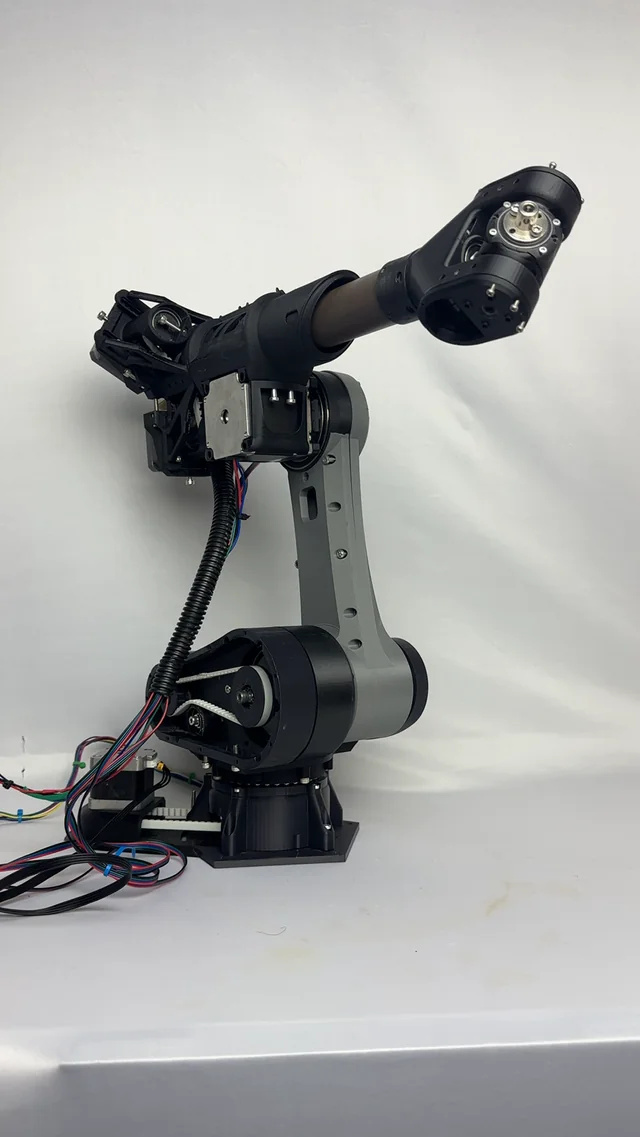
This is a 6DOF robot arm that I finished last year. This project started in 2022 when I was 14 years old, and I finished it when I was 16. It’s fully 3D printed and custom. The base and shoulder are driven by cycloidal gearboxes printed in nylon, the rest of the build was printed in PLA. The part I’m most proud of is the elbow assembly and the differential wrist mechanism. I placed all my motors in the back so they act as counterweights and reduce the torque needed for the elbow. The motion is driven by concentric tubes up to the wrist, where it’s a differential wrist driven by belts. The electronics are fully custom with TMC2209 and TMC2160 motor drivers and an STM32F103 as a microcontroller. It has taught me a lot about each isolated fields of robotics, - mechanical with the gearboxes and mechanical assembly, - electrical with the custom pcb design and electronics - software and control systems with programming in embedded on STM32 microcontrollers in c++ then Rust and inverse kinematics implementations in code. I’m proud of it. I’m currently at the part of controlling it, which is the part I find difficult. I’ve tried inverse kinematics on the microcontroller, but I’m unsure if the STM32F103 is able to handle it. So I had the idea of offloading the computation to a Raspberry Pi or a PC and communicating over UART. another pain point is pin mapping, how do you manage that on complex robots? I’m happy to receive any direction on these subject. submitted by /u/_Rayolo_ [link] [Kommentare]
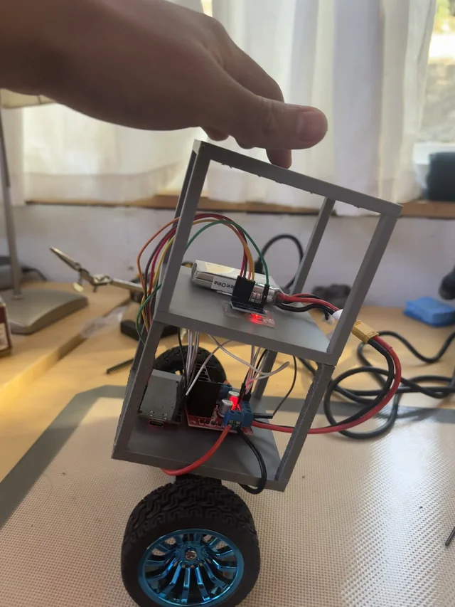
So i’ve created this robot using an ESP32, L298n motor driver, MPU 6050, and powered by a 7.4 2s Lipo Battery. I’ve been having a lot of trouble with the PID tuning, working solely on tuning for 4+ days with no results. I would really appreciate any advice! This is what I currently have: Code: https://docs.google.com/document/d/1wHsZ9ZLWXOu-upoTgflaRj04iTZKkDtYxoTk9kdxAj4/edit?usp=sharingb submitted by /u/bfffornever123 [link] [Kommentare]
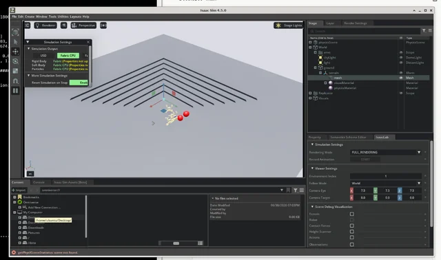
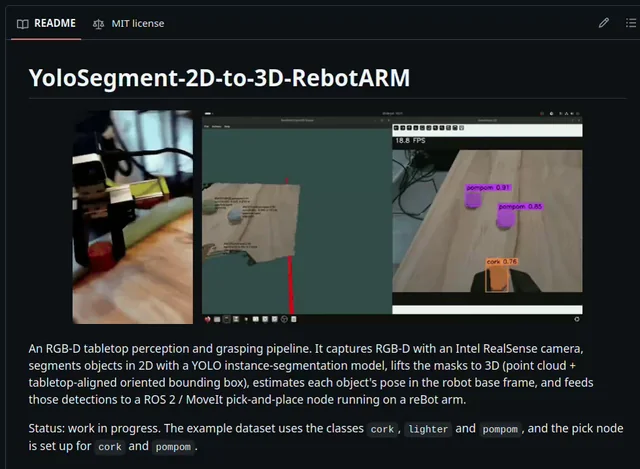
Some of you asked for the full pipeline code, so here it is. https://github.com/danieldoradotalaveron-rb/YoloSegment-2D-to-3D-RebotARM_Pick_and_Place submitted by /u/nettrotten [link] [Kommentare]
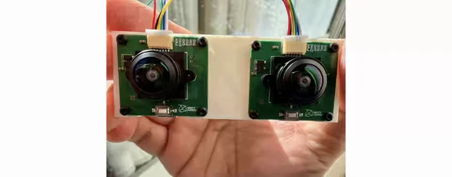
This is my project, Mighty Camera. It is essentially a monocular SLAM camera running entirely on tiny onboard compute. See my past posts for details. Mighty also supports combining multiple cameras and synchronizing them to produce frame-level synced streams. In this setup, I’m using that hardware synchronization to generate depth with SGBM, while it also produces VIO pose. submitted by /u/twokiloballs [link] [Kommentare]

I had a first go, putting together some of our friends in the space + a bit of research. Who’s missing? Feel free to tag your venture in the comments. submitted by /u/Erlapso [link] [Kommentare]
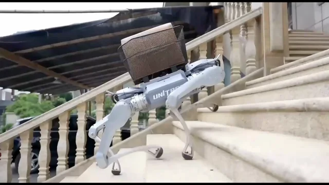
Every quadruped project, from research labs to Boston Dynamics, starts in the same place: a working simulation. Getting there is the slow part. Dozens of joints, the right dependencies, a launchable scene, all configured before you can train a single gait. I skipped it with one prompt to Drift: empty project to a four-legged robot standing in MuJoCo. submitted by /u/airwarmedd [link] [Kommentare]
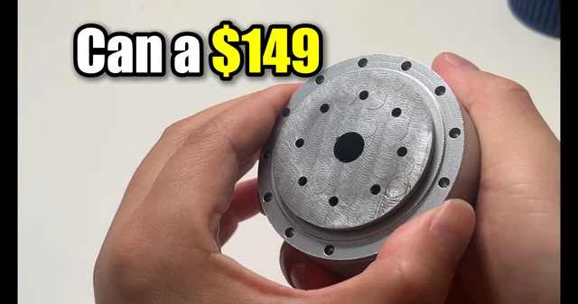
Hey guys. A couple months back I asked this sub for some reality checks on using a 30:1 metal cycloidal to replace 3D printed joints for QDD. The first batch of CNC parts finally showed up. I was honestly expecting the tight machining tolerances to make it bind up, but turning the output flange by hand... the back-drivability is wild. Just for context: we were getting super annoyed with stripping the 3D-printed plastic gears on open-source rigs like the Berkeley Lite and ALOHA. They are awesome projects, but the plastic joints are fragile and a nightmare to maintain. So we designed this as a drop-in replacement (calling it the Starfruit Actuator). Instead of printing two different plastic joint types, we wanted a single unified metal design to simplify the BOM and actually survive dynamic loads. Specs we're rolling with for the final drop: 30:1 ratio (30 teeth, 31 pins) Dual absolute encoders (supports FOC & MIT modes) Fully ODrive-compatible Target price: ~$149 Next up is integrating the motor and driver board, then throwing it on the test bench to see if it survives a 76 Nm torque test without exploding. Fingers crossed lol. Let me know what you think of the machining! All the STEP files, ROS2 nodes, and configs are going to be 100% open source. I'll drop the project link in the comments if anyone wants to track the testing or grab the files when they go live. submitted by /u/External_Wasabi9131 [link] [Kommentare]

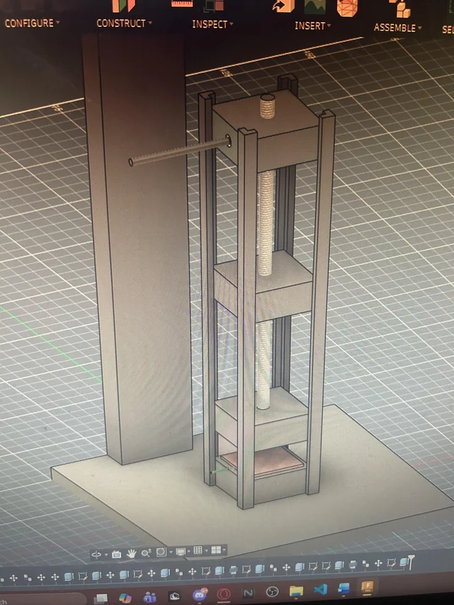
So I want to perform a material characterization study on a material where I need to put it under pressure. I’m in high school and don’t have a mentor or time to ask for access to university labs so I want to make something that can help me get data for cheap. I’m trying to make a linear actuator design and physically build all the parts myself (except for the motor and leadscrew system obviously) but I don’t extensively know how these types of things work. If I was to build something like this (pictures) would there be any significant issues? The cylinder (of which I don’t know what material to make out of) protruding out from the side would be directly connected to the sliding block part of my linear actuator so it pushes that down onto my material. I’m going to be pushing with 50lbs ish max so I’m making the majority of this out of wood. Any tips on making sure it doesn’t get worn out by some slight imperfection over the thousands of trials I’m going to need it for? And also any tips to make it work if something is seriously wrong 😭 And lastly any other tips about doing research studies like this without lab access or a significant mentor would be greatly appreciated. submitted by /u/bount_ [link] [Kommentare]